Stackr Robot Technical Specifications
Reference dimensions, connector pinouts, and wiring diagrams for the Stackr robot kit. Use this page when planning add-ons, writing custom sketches, or checking which Arduino pins are already used by the onboard components (motors, button).
Physical Dimensions
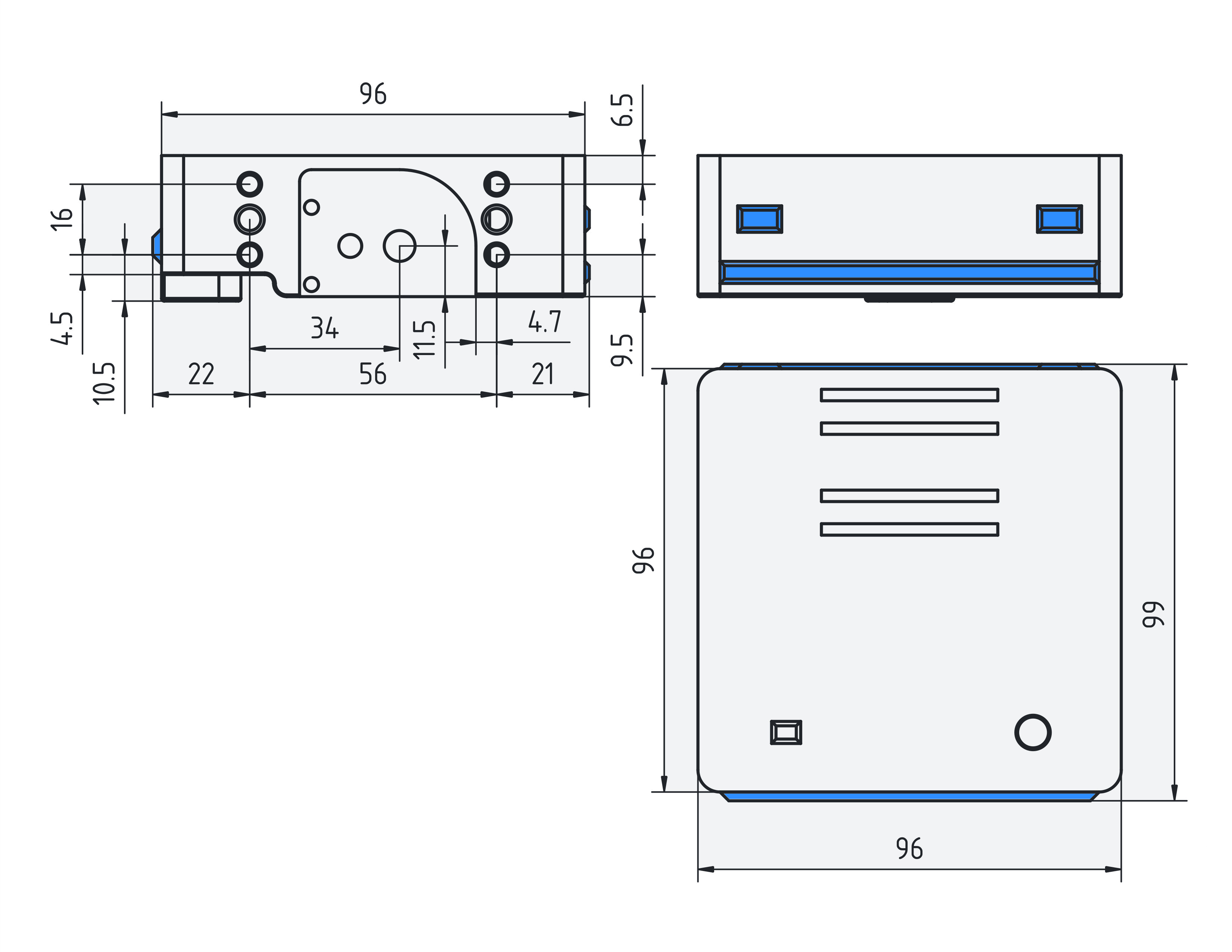
The Stackr chassis is a compact square platform designed for desktop robotics projects. The drawings below list overall length, width, and height, including the motor housings and top cover.
Pinout Summary
Stackr tutorials use the Arduino pin names (D3, A0, and so on) shown in the Arduino IDE for the Nano ESP32. The table below lists the main signals used on a stock Stackr build.
| Function | Arduino pin | GPIO | Notes |
|---|---|---|---|
| Motor driver (TB6612) | |||
| Motor A PWM | D3 | GPIO6 | Right motor speed |
| Motor A IN2 | D4 | GPIO7 | Right motor direction |
| Motor A IN1 | D5 | GPIO8 | Right motor direction |
| Motor B IN1 | D6 | GPIO9 | Left motor direction |
| Motor B IN2 | D7 | GPIO10 | Left motor direction |
| Motor B PWM | D8 | GPIO17 | Left motor speed |
| Driver STBY | VIN | VIN | Standby = high (driver enabled) |
| Servo port (rear) | |||
| Servo 1 signal | D10 | GPIO21 | Primary servo (eg. Arm control) |
| Servo 2 signal | D9 | GPIO18 | Secondary servo (eg. Scoop/Claww control) |
| Servo port power | VIN | VIN | Battery voltage in |
| I2C port (rear) | |||
| SDA | D21 / A4 | GPIO11 | I2C data (e.g. Lidar) |
| SCL | D22 / A5 | GPIO12 | I2C clock |
| Port 3V3 | 3V3 | 3V3 | 3.3 V out for sensors |
| Input | |||
| Onboard button | D2 | GPIO5 | User definedb button |
| RC receiver (optional with adapter) | |||
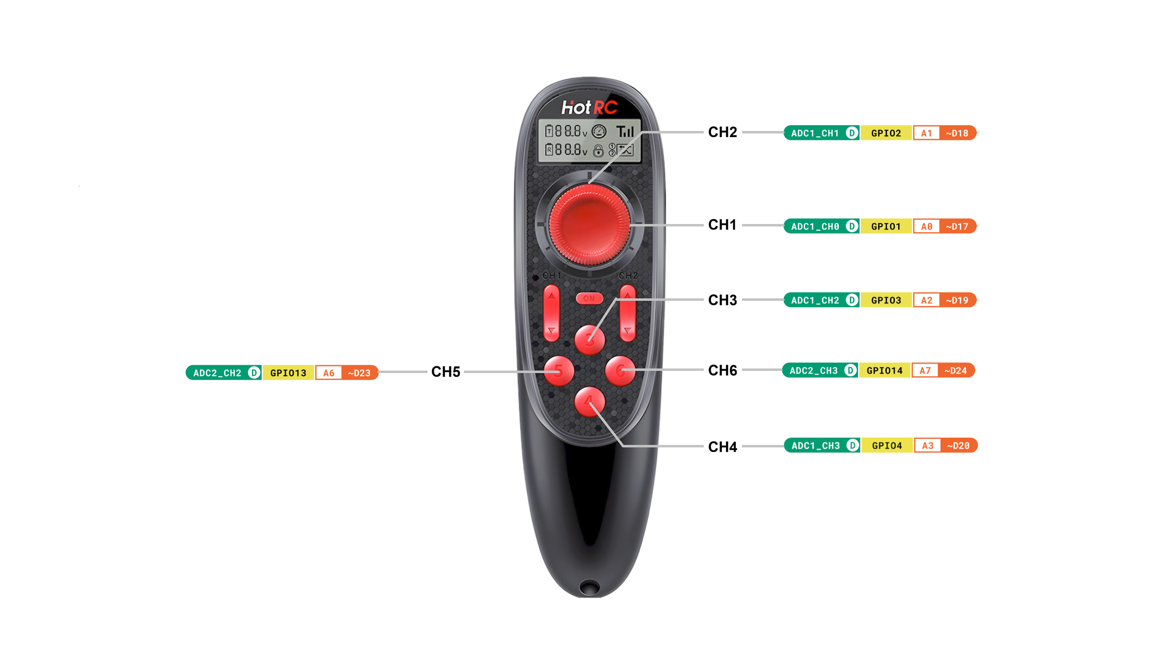
| Channel 1 | A0 / D17 | GPIO1 | Left–right joystick (steering) |
| Channel 2 | A1 / D18 | GPIO2 | Forward–back joystick (throttle) |
| Channel 3 | A2 / D19 | GPIO3 | Up button |
| Channel 4 | A3 / D20 | GPIO4 | Down button |
| Channel 5 | A6 / D23 | GPI013 | Left button |
| Channel 6 | A7 / D24 | GPIO14 | Right button |
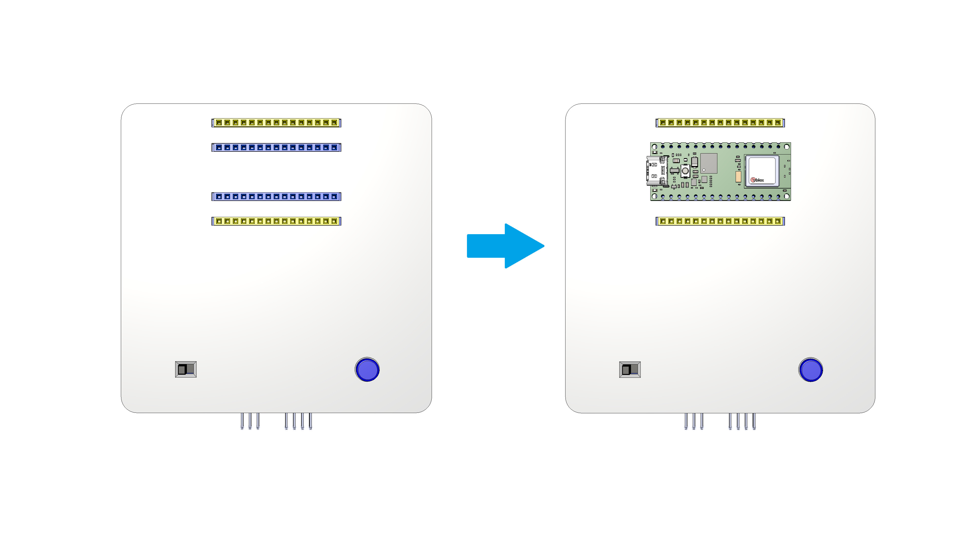
Pins not listed are generally available for your own circuits. They can be accessed using the yellow connectors on the top of the chassis. Avoid reusing motor pins when stacking multiple add-ons. The servo pins and I2C pins can be used as general purpose pins assuming they are not used for their primary purpose.
Diagrams & Pinouts
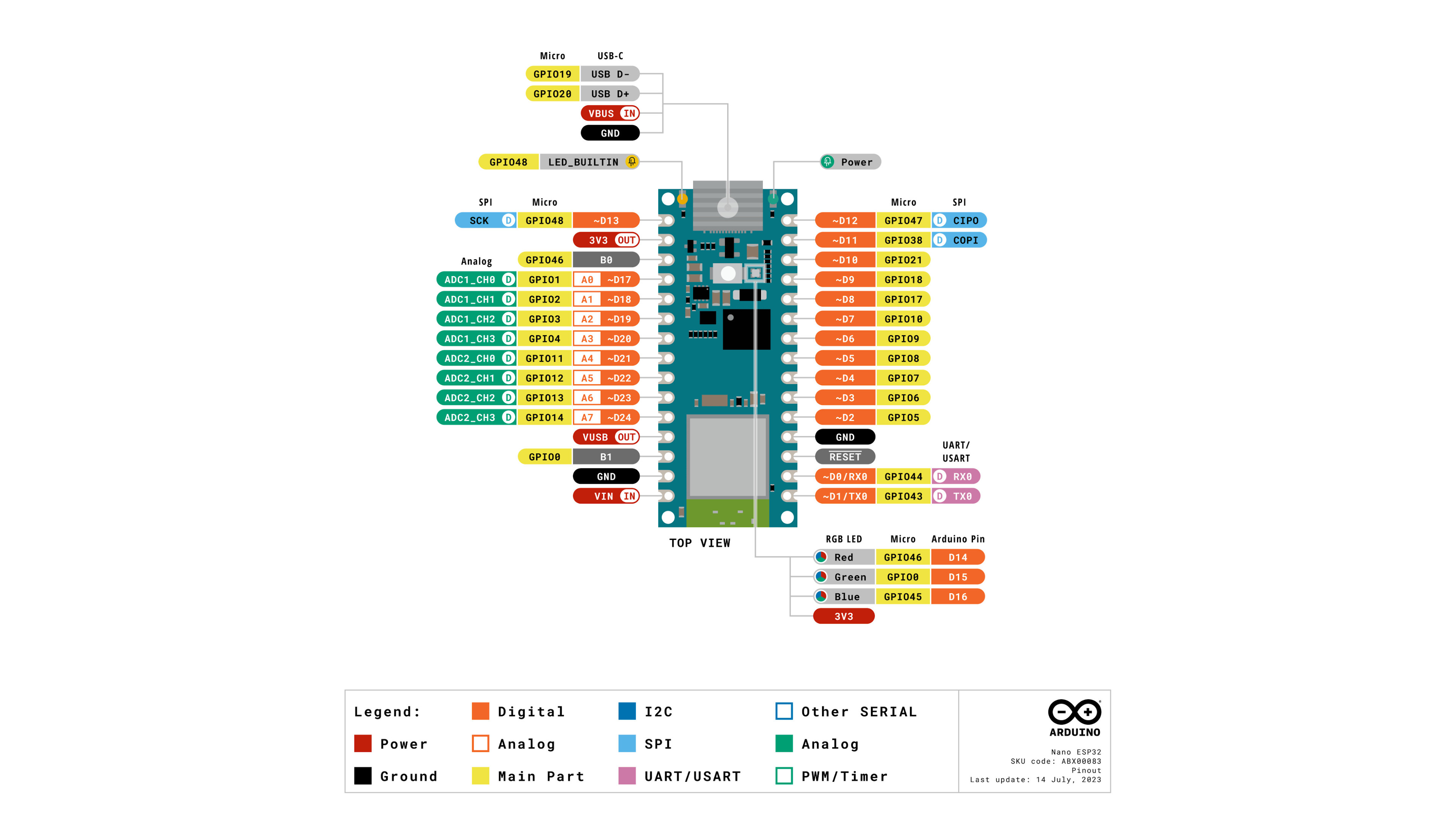
3V3, VIN, GND), digital pins D0–D24, analog A0–A7, and special functions (I2C, SPI, UART). Cross-reference this chart when a tutorial refers to a pin that is not drawn on the Stackr-specific diagrams.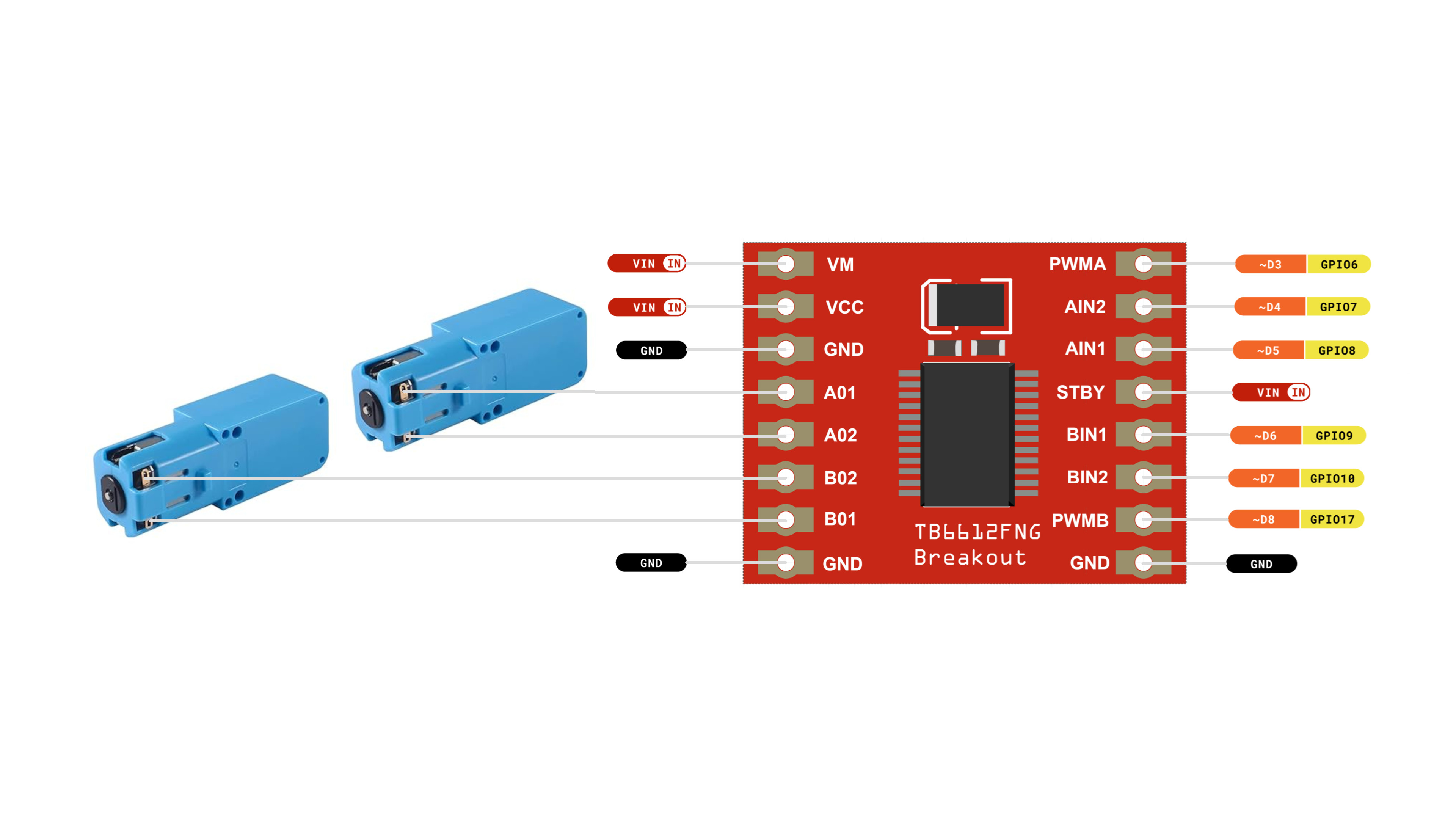
A01/A02; motor B (left) uses B01/B02. Control lines map to D3–D8 and D9 for standby, matching the motor tutorial sketches.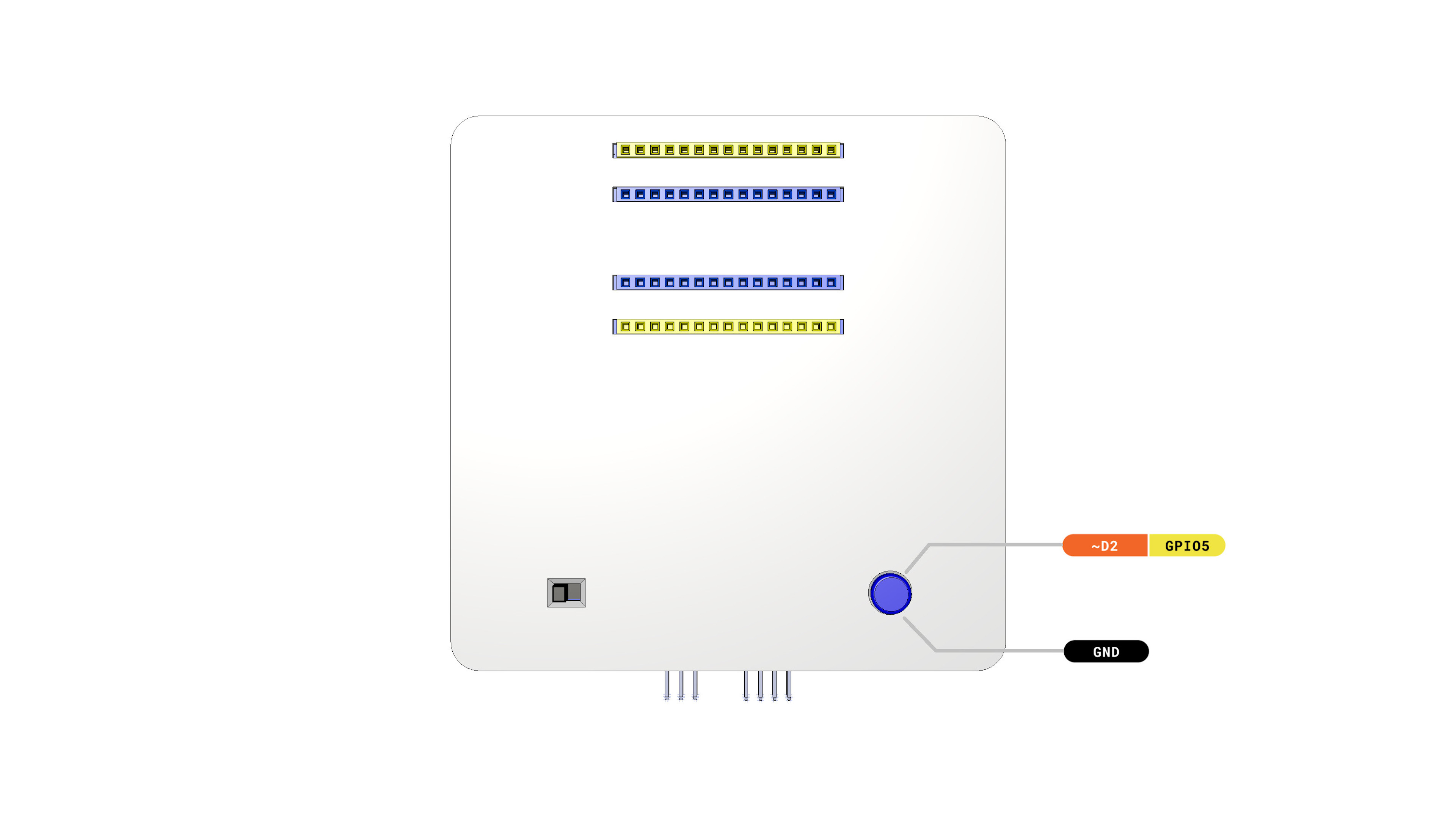
D2 (GPIO5) to GND when pressed. The small slide switch on the lower left is the main power switch for the robot.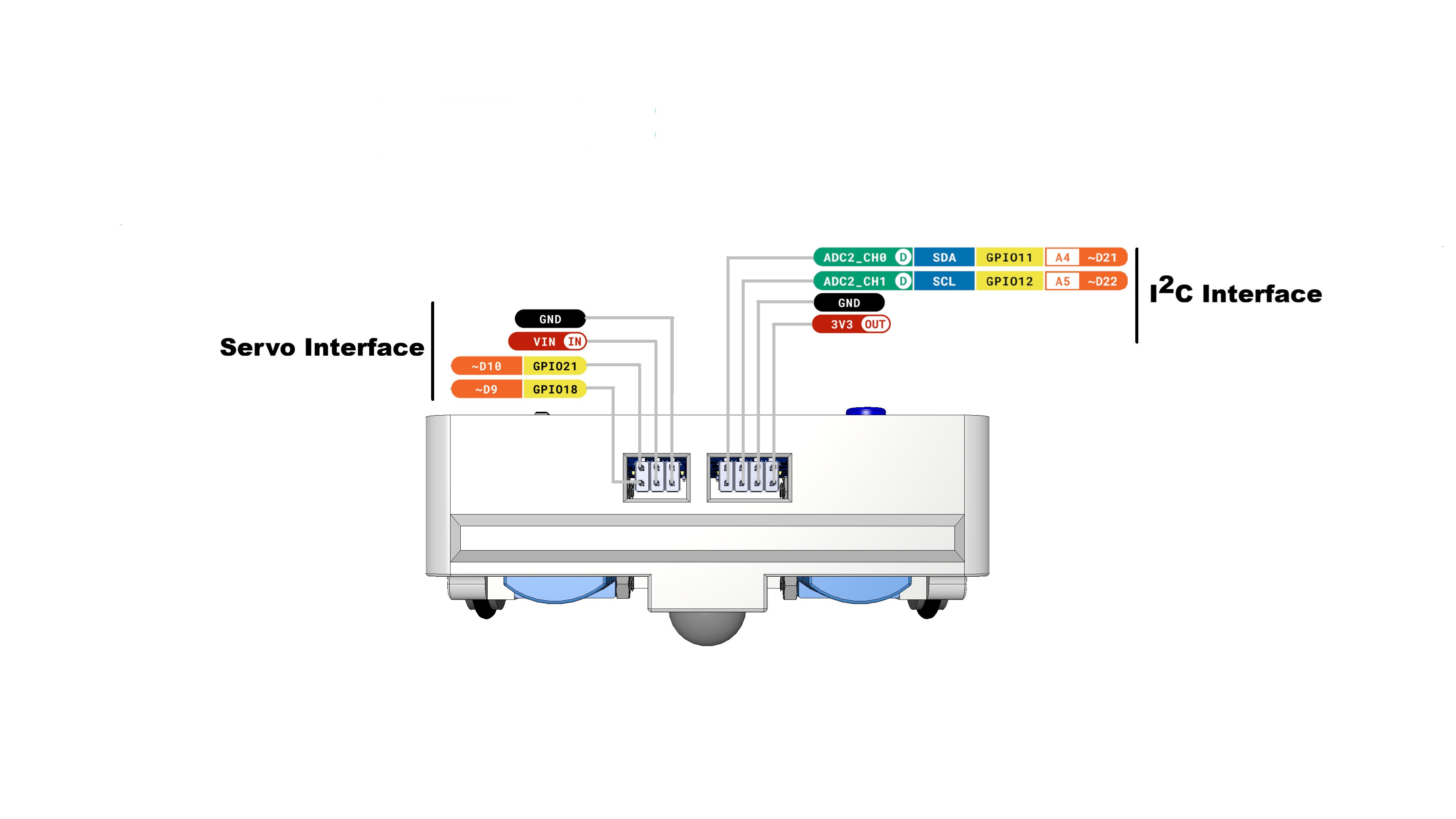
D10 and D9, plus VIN and GND for servo power. I2C interface (right): SDA on D21, SCL on D22, with GND and regulated 3V3 out for sensors such as the Lidar module.